Engineering Graphics [SPPU]
Objectives for the subjectEngineering Graphics [SPPU] is to impart and inculcate proper understanding of the theory of projection.
To impart the knowledge of reading a drawing. To improve the visualization skill. To teach basic utility of computer aided drafting (CAD) tool. Outcomes for the subject Engineering Drawing Learner will be able to apply the basic principles of projections in 2D drawings. Apply the basic principles of projections in converting 3D view to 2D drawing. Read a given drawing. Visualize an object from the given two views. Use CAD tool to draw different views of a 3D object. Use CAD tool to draw an object in 3D.
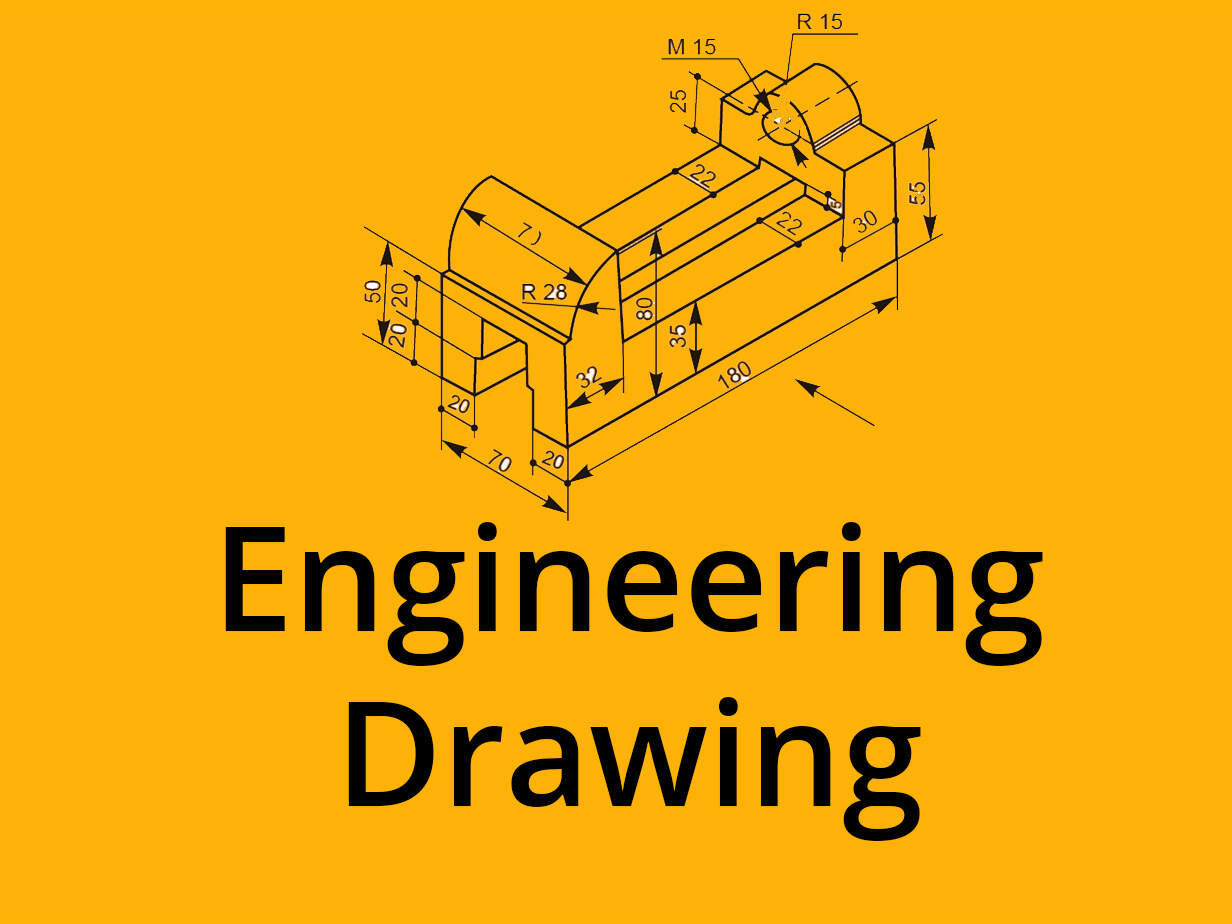
An engineering drawing is a type of technical drawing that is used to convey information about an object. A common use is to specify the geometry necessary for the construction of a component and is called a detail drawing. Usually, a number of drawings are necessary to completely specify even a simple component. The drawings are linked together by a master drawing or assembly drawing which gives the drawing numbers of the subsequent detailed components, quantities required, construction materials and possibly 3D images that can be used to locate individual items. Although mostly consisting of pictographic representations, abbreviations and symbols are used for brevity and additional textual explanations may also be provided to convey the necessary information. The process of producing engineering drawings is often referred to as technical drawing or drafting (draughting). Drawings typically contain multiple views of a component, although additional scratch views may be added of details for further explanation. Only the information that is a requirement is typically specified. Key information such as dimensions is usually only specified in one place on a drawing, avoiding redundancy and the possibility of inconsistency. Suitable tolerances are given for critical dimensions to allow the component to be manufactured and function. More detailed production drawings may be produced based on the information given in an engineering drawing. Drawings have an information box or title block containing who drew the drawing, who approved it, units of dimensions, meaning of views, the title of the drawing and the drawing number.
Module Introduction to Engineering Drawing consist of the following subtopics Types of Lines, Dimensioning Systems as per IS conventions. Engineering Curves: – Basic construction of Cycloid, Involutes and Helix (of cylinder) only. Introduction to Auto CAD: – Basic Drawing and Editing Commands. Knowledge of setting up layers, Dimensioning, Hatching, plotting and Printing. Module Projection of Points and Lines consist of the following subtopics Lines inclined to both the Reference Planes (Excluding Traces of lines) and simple application based problems on Projection of lines. Projection of Planes:- Triangular, Square, Rectangular, Pentagonal, Hexagonal and Circular planes inclined to either HP or VP only. (Exclude composite planes). Projection of Solids:- (Prism, Pyramid, Cylinder, Tetrahedron, Hexahedron and Cone only) Solid projection with the axis inclined to HP and VP. (Exclude Spheres, Composite, Hollow solids and frustum of solids). Use change of position or Auxiliary plane method Section of Solids:- Section of Prism, Pyramid, Cylinder, Tetrahedron, Hexahedron & Cone cut by plane perpendicular to at least one reference plane.( Exclude Curved Section Plane). Use change of position or Auxiliary plane method Development of Lateral Surfaces of Sectioned Solids:- Lateral surface development of Prism, Pyramid, Tetrahedron, Hexahedron, Cylinder, Cone with section plane inclined to HP or VP only. (Exclude DLS of a solid with a hole in it and Reverse Development). (Exclude Reverse Development).
Module Orthographic and Sectional Orthographic Projections consist of the following subtopics Different views of a simple machine part as per the first angle projection method recommended by Full or Half Sectional views of the Simple Machine parts. Drawing of orthographic projections using Auto CAD. Isometric Views:- Isometric View/Drawing of blocks of plain and cylindrical surfaces using plain/natural scale only. (Exclude Spherical surfaces). Drawing of Isometric views using Auto CAD.Reading of Orthographic Projection. Orthographic Reading using Auto CAD. Introduction to 3D in AutoCAD Working in 3-dimensions, Viewing 3D Objects, Basic wireframe models, Extruding, simple revolved objects. Boolean operations.
Suggested Texts Books for the subject Applied Chemistry ‐II by Mumbai University are as follows Text Books.N.D. Bhatt, “Engineering Drawing (Plane and solid geometry)”, Charotar Publishing House Pvt. Ltd. 2 N.D. Bhatt & V.M. Panchal, “Machine Drawing”, Charotar Publishing House Pvt. Ltd. Suggested References Books for the subject Applied Chemistry ‐II by Mumbai University are as follows M.B Shah & B.C Rana, “Engineering Drawing”, Pearson Publications. P.J. Shah, “Engineering Graphics”, S Chand Publications. Dhananjay A Jolhe, “Engineering Drawing” Tata McGraw Hill. Prof. Sham Tickoo (Purdue University) &GauravVerma, “(CAD Soft Technologies): Auto CAD 2012 (For engineers and Designers)”, Dreamtech Press NewDelhi.
Prepare For Your Placements: https://lastmomenttuitions.com/courses/placement-preparation/
![]()
/ Youtube Channel: https://www.youtube.com/channel/UCGFNZxMqKLsqWERX_N2f08Q
Follow For Latest Updates, Study Tips & More Content!
Course Features
- Lectures 21
- Quiz 0
- Duration 50 hours
- Skill level All levels
- Language English
- Students 242
- Assessments Yes
Curriculum
- 1 Section
- 21 Lessons
- 52 Weeks
Expand all sectionsCollapse all sections
- Videos21
- 1.1Involute Curve10 Minutes
- 1.2Involute Curve Numerical part 212 Minutes
- 1.3Methods to turn on SCR10 Minutes
- 1.4Orthographic Projection Full Basics Concept13 Minutes
- 1.5Orthographic first angle25 Minutes
- 1.6First Angle Method & Dimensioning Rules15 Minutes
- 1.7Introduction to Third Angle Method11 Minutes
- 1.8Third Angle Method Solved Example25 Minutes
- 1.9Orthographic Projection Numerical17 Minutes
- 1.10Orthographic Projection Numerical Part 222 Minutes
- 1.11Sectional Orthography16 Minutes
- 1.12Sectional View Solved Example19 Minutes
- 1.13Sectional Orthographic Projection Solved9 Minutes
- 1.14Isometric Projection13 Minutes
- 1.15ISometric View10 Minutes
- 1.16ISometric View Numerical19 Minutes
- 1.17ISometric View Numerical part 210 Minutes
- 1.18Simple Isometric Sum11 Minutes
- 1.19Isometric Projection With Solved Example15 Minutes
- 1.20Isometric Projection Numerical13 Minutes
- 1.21Isometric Projection Numerical part 212 Minutes


![Engineering Graphics Design [GTU]](https://www.informaltuitions.in/wp-content/uploads/2021/03/Engineering-Graphics-Design-GTU-400x250.jpg)
